Speed density

4GTuner

Help Support 4GTuner:

Ian91

Well-Known Member
Joined
Jun 25, 2010
Messages
1,651
Location
Pomona, Sunshine Coast, QLD
Hi fellas, thinking of going over to a speed density setup now I've got the gsr running with the Evo 8 mr ecu.

I've done some googling but most stuff seems to be US related and I don't know what model is best to use as a reference.

Anyone on here running an sd setup that can recommend what parts to use and which way to set it all up?

Links to parts and guides much appreciated. Also seen some people posting links of ecu maps which have been fondled to suit sd, anyone know which one to use?

Don't have evoscan just yet but will make sure I have that before going ahead with this.

Thanks

Ian
 
You need a bung welded onto the pipe that leads to TB then you need to put a inlet temp sensor in that.
You also need a 3/4 bar map sensor which reads off the inlet mani..how its wired up has got me fucked but.
I can take pics of mine if need be?
 
The "EDM/JDM Harness" is for European or Japanese model Evos that did not come with a MAP sensor from the factory. It adds a connector for a GM Style MAP Sensor or Stock Style MAP Sensor. You simply swap Pin 51 (Barometer) to Pin 92 (MAP) and follow the directions below.

This is what I think would be the one you would use...
 
evo-gsr said:
You need a bung welded onto the pipe that leads to TB then you need to put a inlet temp sensor in that.
You also need a 3/4 bar map sensor which reads off the inlet mani..how its wired up has got me fucked but.
I can take pics of mine if need be?
Pics would be great, when ever you've got time, thanks. Also if your tuner used a patch loom to set it up, any chance you can ask him which one and where from?

Cheers
 
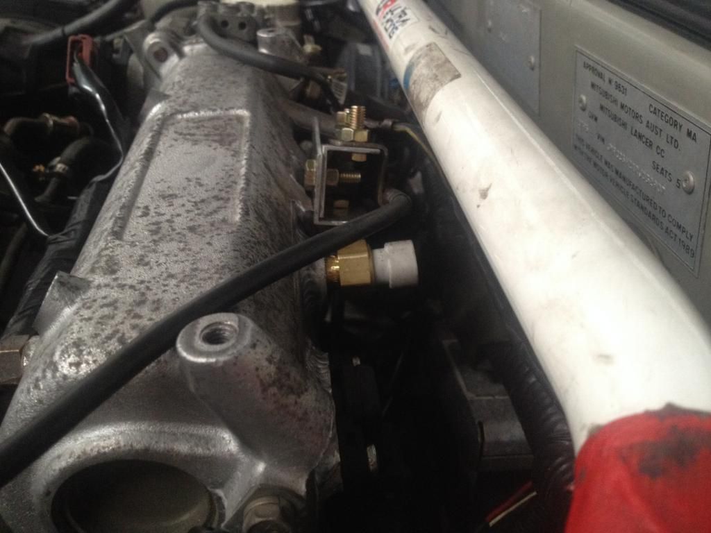
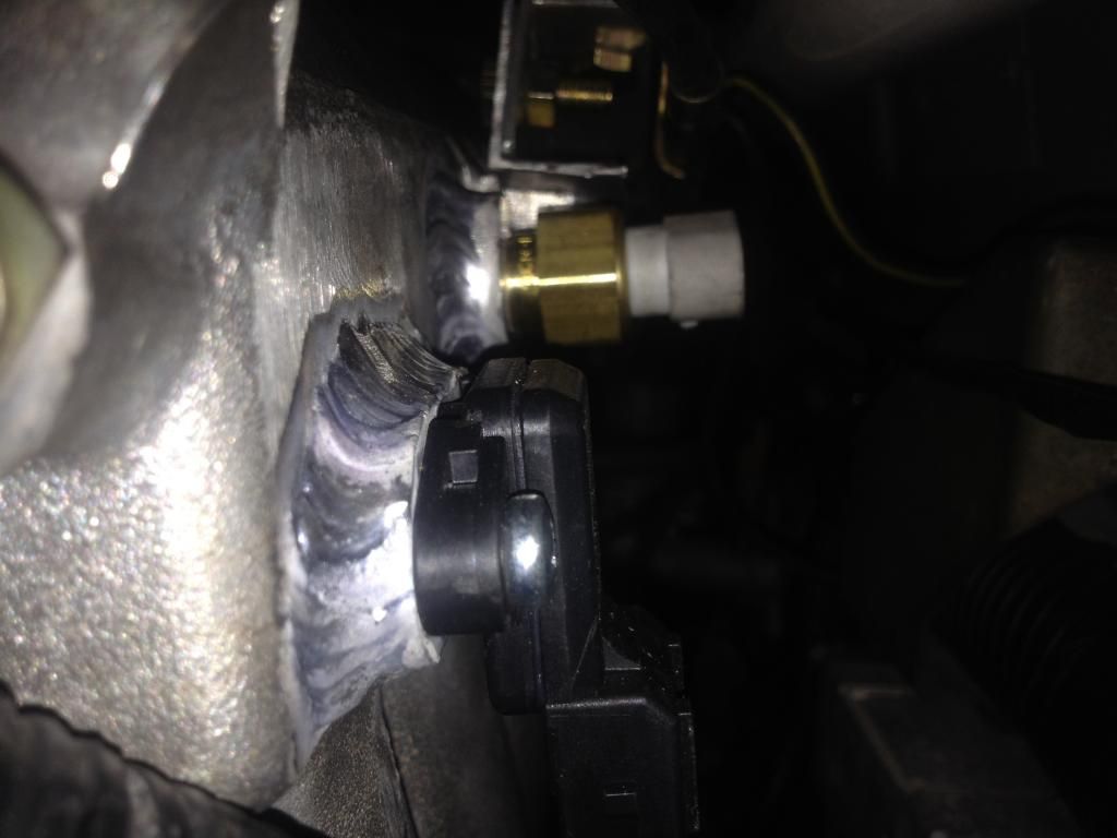
heres now mines setup this is in a 4g92 manifold which is a factory speed density setup i have modified it alil

IMG_0678_zps47d630a0.jpg


IMG_0679_zps027e931e.jpg


the map sensor is a 3 bar evo x style unit on a adapter fitting available on ebay (that needed modification) welded in the manifold where the factory unit would normally thread in.

the IAT is a gm style intake temp sensor on a bung welded in to the manifold. std it is on the front injector side above and between runners number 1 and 2 almost directly opposite the map sensor position. some will say it is suppoes to go ahead of the throttle body but factory mine was behind so i went behind to me this just means it can kinda go anywhere. to me you'd want it somewhere after the intercooler as close to the throttle body or in the intake manifold for the most accurate measure of actual intake temps as possible
 
leadfoot said:
heres now mines setup this is in a 4g92 manifold which is a factory speed density setup i have modified it alil

IMG_0678_zps47d630a0.jpg


IMG_0679_zps027e931e.jpg


the map sensor is a 3 bar evo x style unit on a adapter fitting available on ebay (that needed modification) welded in the manifold where the factory unit would normally thread in.

the IAT is a gm style intake temp sensor on a bung welded in to the manifold. std it is on the front injector side above and between runners number 1 and 2 almost directly opposite the map sensor position. some will say it is suppoes to go ahead of the throttle body but factory mine was behind so i went behind to me this just means it can kinda go anywhere. to me you'd want it somewhere after the intercooler as close to the throttle body or in the intake manifold for the most accurate measure of actual intake temps as possible
Thanks Kyle, all info helps, how are yours wired in, patch cable or straight to ecu?
 
patch cable to the AFM plug that i made myself by sacrificing an AFM for the male connector

all the wires needed are in there
the IAT is a factory pin in the ecu and the map goes to the pin that the afm signal would have normally gone to but i am running an aftermarket ecu so i designated these pins as those items

for reference (from evo /gsr pinout)
pin 52 on ecu is IAT (from maf) (red black trace)
and pin 70 is afm MAF signal )white black trace)
pin 61 for +5v for MAP (green with red trace)
black is earth for both sensors

you with have 3 pins remaining not used
+12v power (red) (i used this for my mivec solenoid power)
barrometric pressure (pink) (used to trigger solenoid by ecu)
reset (blue) will become my flex fuel signal wire

i wired this way as that was the closet i could figure to a factory configuration for those sensors
 
Good thread Ian, I'm yet to do this to the rvr but was just gunna copy the 5, the thread will save me save pulling it apart hopefully
 
Thanks Kyle, wire colours and pinout will help.

Byby5l haha no worries, these threads are here to help anyone reading.

Cranked, good tip, makes sense, I read somewhere that it should be up to 6 inches before tb, for the same reason I guess? Or maybe it was 6 inches or more from BOV, got myself confused now.

After reading the above links and checking out some of the parts available I might go for the ecm stuff and see if I can get it as a package, may even get the ethanol cable for later on.

But if anyone knows a local source for the required bits I don't mind making my own patch loom or just cut and shut the existing wires, cars never going back to stock so doesn't bother me lol.

Also anyone have any experience with any of the ecu maps that are available online to get sd going? Or does anybody have a map they could email that I can put on my ecu as a start?

Cheers, keep any and all info coming guys.
 
How soon are you doing it? Im tuning an evo 6 with an e8 gsr ecu and speed density next week or a gsr with an 8mr ecu on speed density in about 6 weeks. Can probably send you something to start with.
 
A guy on here is selling connectors. Cant give you a pinout for the afm but the wore colors are the same as listed. Ecu Pinout can be found in the dropbox link in the tech files thread i have pinned at the top of this section.
 
Be calm man i did say that other would say intake pipe mine is only in the mani because it was the easiest at the time its also where the factory unit was so it couldnt be that bad. I am not saying it should go there without exception. If the factory thought it was a good place for it it cant be that bad. You can actually see the factory unit in the first photo on the front side. But in saying that other manutacturers have it in the intake pipe this is why i said it could go anywhere within reason som places will obviously be beter than others and im not arguing that fact. Caged provided a good valid reason why before the tb is beter. As i would agree heat soak could be an issue. Remember this was initially a n/a application for this setup so the extra heat from turbo would make cageds reasoning why i would agree in the cooler piping. But my point is in the manifold is not the end of the world
 

Latest posts

Back
Top